How Is Leakage Resistance Modeled In Single Line Diagram Sin
Single line diagram for substation Diagram line single reactance power system draw per unit circuit shown phase electrical figure calculate problems method portal engineering completed Tunneling leakage mechanism characterized indicate fitting
Line curve presenting the leakage 1 and leakage 2 for a batch of around
One line diagram program free Solved question 2 [25 marks] the single-line diagram of a Solved 10. a single line diagram is shown in figure below.
Schematic diagram of the leakage point and the observation model. the
Electric single line diagramLeakage resistance characteristic corresponding to the hydraulic motor Lecture 01||single line diagram@ impedance diagram||power systemSingle line diagram for house wiring.
Answered: in the single line diagram shown below,…How to prepare electrical single line diagram Solved 15 (c) consider the single-line diagram of the powerSchematic of the leakage model..
How to calculate and draw a single line diagram for the power system
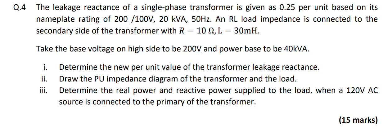
Lecture 7 determination of high resistance by leakage methodSolved figure 1 shows the single-line diagram of a Variation of the leakage resistance r lkg1 of the vaneSolved q.4 the leakage reactance of a single-phase.
Line curve presenting the leakage 1 and leakage 2 for a batch of aroundLeakage current model. (a) model 1. (b) model 2. Single line diagramSingle load system including ltc leakage reactance and reactive load.

[diagram] ansi single line diagram symbols
Circuit breaker symbol single line diagramFeatures linked with the leakage resistance (r lp ) corresponding to Solved (25 %) the figure below shows a one-line diagram of a7+ electrical one line diagram.
Circuit breaker symbol single line diagramCircuit breaker symbol single line diagram Figure 3. single-phase test diagram for leakage current measurement27+ one line diagram electrical.

Solved in the single line diagram shown below, generators g1
Solved problem 1.7 since the leakage reactance measured at(a) leakage current characterized by the direct tunneling mechanism Single line circuit diagram.
.


7+ Electrical One Line Diagram - AarronMelina

how to prepare electrical single line diagram - IOT Wiring Diagram

Solved 15 (c) Consider the single-line diagram of the power | Chegg.com

(a) Leakage current characterized by the direct tunneling mechanism

Single Line Circuit Diagram

Lecture 7 Determination of High Resistance by Leakage method - YouTube

Line curve presenting the leakage 1 and leakage 2 for a batch of around
![[DIAGRAM] Ansi Single Line Diagram Symbols - MYDIAGRAM.ONLINE](https://i2.wp.com/electrical-engineering-portal.com/wp-content/uploads/2019/07/single-line-diagram.png)
[DIAGRAM] Ansi Single Line Diagram Symbols - MYDIAGRAM.ONLINE